What a thickness measurement needs
A thickness is a distance between two surfaces along one direction. On a scan that means three facts for every point: where the near surface is, where the far surface is along the same direction through the material, and what the nominal is at exactly that place — because on a cast, moulded or bent part the nominal wall is rarely constant. Leave one of the three out and the number is a guess.
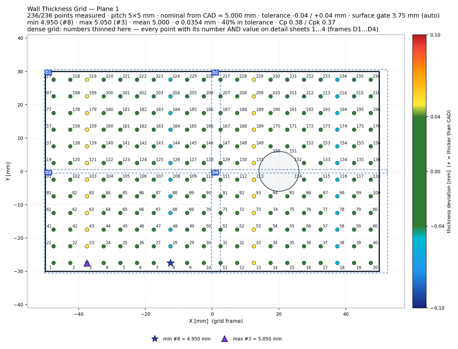
The Wall Thickness Grid uses the Plane Grid lattice on the near face and casts three rays per lattice point along the local surface normal: a near ray (surface gate), a far ray through the material inside a thickness window, and a CAD ray that reads the nominal face-to-face on the CAD model itself.
Why the nominal is read on the CAD, not from the fitted plane
An early version read the nominal from the plane fitted to the scan. On a plate bent by two millimetres that plane is nowhere near the CAD face, so the nominal varied from point to point and the capability figures were meaningless. The engine now finds the CAD face closest to the point within a gate, reads the back face from that CAD face, and the nominal is independent of how the measured element sits on the scan.
On cylinders and cones the CAD tessellation itself is not good enough: a STEP exported with a coarse angular deflection represents a 2.000 mm tube wall as chords, and chord-to-chord the wall reads 1.978 – 1.998 depending on the angle. Every hit is therefore snapped to the analytic surface of the catalogued face when it belongs to one; a rival face inside the snap tolerance leaves the mesh value in place rather than choosing.
- Nominal from the drawing value (one number) or face-to-face on the CAD (per point)
- Analytic snap on cylinders, cones and spheres from the STEP catalogue
- The report states the nominal source: mesh, analytic or mixed
Refusals, per point
Three situations produce no thickness. A one-sided scan — the far face was never captured — gives "no far surface" and a single-sided warning on the run. A far face that the ray meets at a steep angle gives "far oblique"; the thickness along the normal would not be the wall. A CAD without a back face behind the point gives "no nominal" unless the drawing value mode is used. Two scan surfaces that both satisfy the window give "ambiguous", not the nearer one.
Each refusal is a row in the point table with its reason, and a grey point on the sketch. Summary rows (min, max, mean, Cp / Cpk) are computed from the measured points only and are themselves N/A below a minimum count.
One-sided tolerances and capability
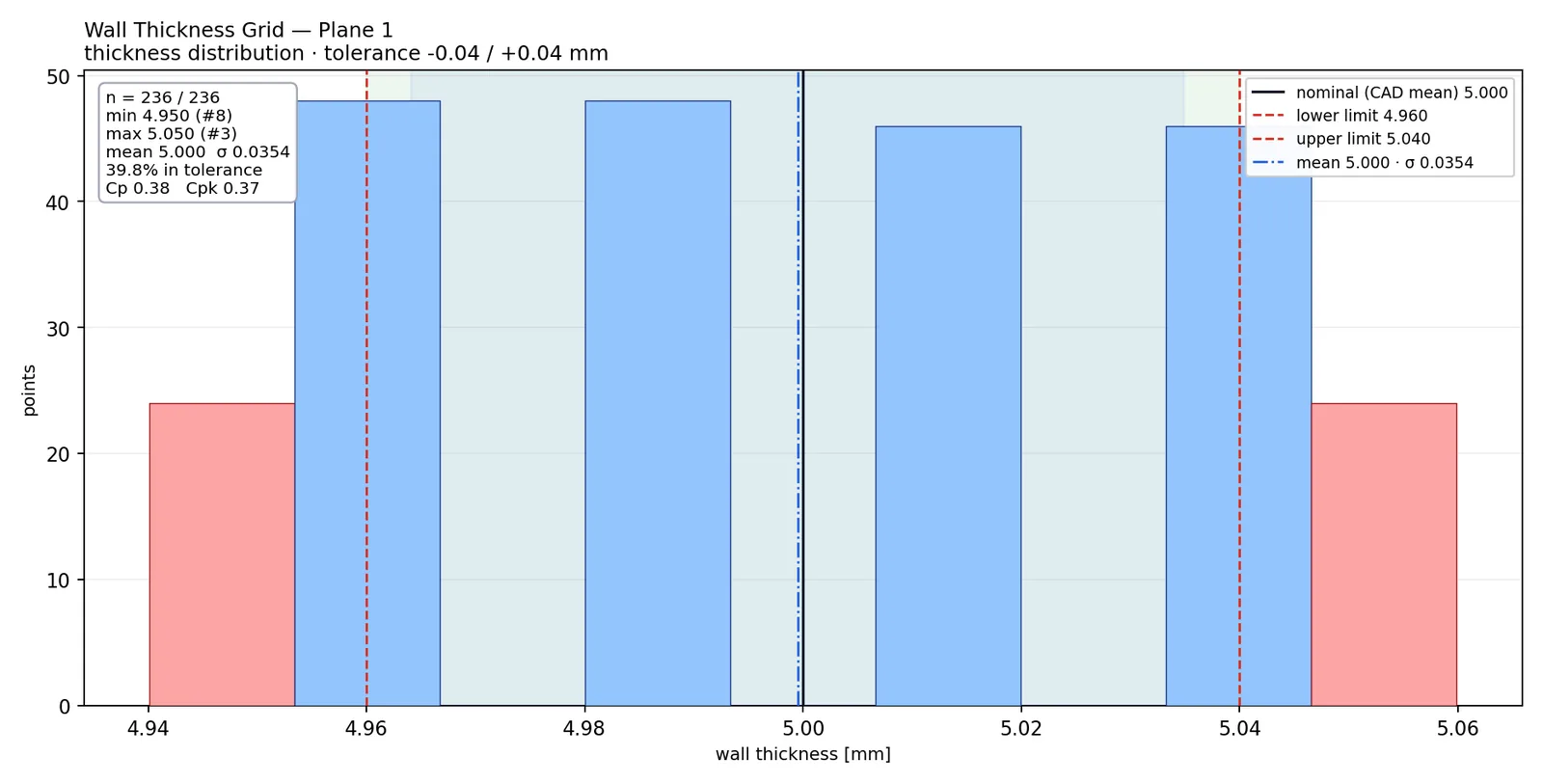
Many wall callouts are one-sided: a minimum wall and nothing above. The grid accepts an open side — the row is judged against the one limit, carries no asymmetric stamp and says so in its note. Cp and Cpk are reported only when both limits exist and at least thirty points were measured; with one limit the summary shows the margin to that limit instead.
The minimum, maximum and mean rows get stable balloons (N, N_1, N_2) and every point row is numbered from its lattice position, so a series of parts reports the same point under the same balloon.
Pipes, housings and bent plates
On a cylindrical or conical face the rays follow the local normal and the material side is detected automatically: a tube read from the outside and the same tube read from the inside give the same wall. A bent sheet is handled by widening the surface gate once (automatic gate only — a typed gate is never widened) and by pairing near and far faces around the CAD face rather than around the fitted plane. On a housing the CAD ray finds the back face behind each point, so ribs and bosses get their own nominal.